


| Released hardware by Bally, not including the Bally Professional Arcade console. |
 |
The Lil' White Ram is a 32K memory expansion unit released in March of 2008. |
_tn.jpg)
|
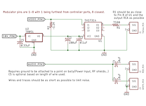
ASTEC UM1291-1 RF Modulator PC Board Layout, Schematics, and Datasheet Michael Matte, National Semiconductor and ASTEC International Limited This document includes various pieces of information about the ASTEC UM1291-1 RF modulator, the original modulator used in the Bally Arcade/Astrocade. Included here is the PC board layout, schematic, an excerpt from the LM1889 TV Video Modulator datasheet, and ASTEC's internal product specification. |
|
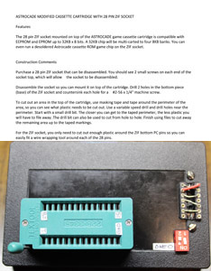
Astrocade Cartridge Modified with 28-Pin ZIF Socket. MCM Design. Dec. 2020. Two pages of instructions on how to modify an Astrocade cartridge to use a ZIF socket. There are additional references attached to this documentation that include six photos of the cartridges interior and exterior and three drawings (ZIF electronic schematic, standard EEPROM/EPROM pin layouts, and two reroute socket examples). The 28-pin ZIF socket mounted on top of the ASTROCADE game cassette cartridge is compatible with EEPROM and EPROM up to 32KB x 8 bits. A 32KB chip will be multi-carted to four 8KB banks. You can even run a desoldered Astrocade cassette ROM game chip on the ZIF socket. The ZIF socket has 5 pins wired to the neighboring reroute socket to allow a user to run various types of chips. There is room on the reroute socket to wire 2 more ZIF pins if a builder desires to do that. The original two-page RTF document, six pictures and three PNG files that make up this pdf document can be downloaded, in needed, here: |
|
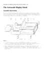
Astrocade Display Kiosk Assembly Instructions - Santa Cruz Wire and Mfg. Co. This is the set of instructions used to build an Astrocade point-of-purchase display unit (AKA as Astrocade Store Kiosk) . Also included are scanned pictures of the drawings of the Astrocade kiosk in various stages of assembly. |
|
64K RAM Board Manual - R&L Enterprises The documentation, including schematics, for this monster Astrocade RAM board. There is no actual Table of Contents, but here is what is included in the manual: 1) General Hardware Features 2) General Hardware Features NOT Included 3) Hardware Options 4) Addressing Ranges 5) PCB Layout 6) Power Supplies 7) Write Protect Installation 8) Routines for Accessing Upper Address Ranges With BASIC 9) Language Memory Locations 10) Useful Language Location Numbers 11) Installation 12) Precautions and Standard Operating Procedures 13) Circuit Description 14) Circuit Operation (See Schematic) 15) 50-Pin Bus Signals 16) Magic Memory 17) Intergalactic Politics (Memory Management) 18) 64K RAM Board Schematic |
_1_of_2.gif)
_2_of_2.gif)
_1.gif)
_Video.gif)
|
Astrocade Add-Under Blueprints - Astro-Vision These are four Add-Under blueprints from April 1982. These GIF files are large (24" x 36"). If you have trouble viewing them, then save them locally to your hard drive and don't view them on the Internet. High-Res TIFF versions of these blueprints are available here. |
(April_2022)_tn.jpg) |
"Astrocade Keypad Matrix" By MCM Design. April 2022. This document serves a dual intent; providing information to help an Astrocade user who wants to rewire an upgraded remote 24-key keyboard to be compatible as a substitute for the Astrocade built-in keypad or desires to strip down the keypad to repair a keypad matrix issue. This is a keypad matrix document in RTF format, plus photos. Michael expanded his commentary on the matrix repair section in this doc, so its more useful. He used the Astrocade Keypad Repair doc already posted on the Bally Alley website, plus this new keypad matrix doc as consultants to repair an Astrocade keypad with two broken keypad buttons and two disconnected matrix row overlays. The two documents are really helpful and clear enough to follow for someone who has some kind of technical background. This article refers to some pictures of the keypad matrix, which are here:
|
(Barry Ellerson)_tn.jpg) |
"Kludge Board Installation and Modification" By Barry Ellerson. 1981. ARCADIAN 3, no. 9 (Jul. 09, 1981): 100. (Advertisement) If your Bally Arcade/Astrocade unit has these symptoms: screen tearing, loss of horizontal sync on warm-up, unit goes dead (or keeps resetting after warm-up), the following modifications will correct them. If you unit went completely dead following symptoms these modifications will probably repair it. The ad for this kit reads, "Clock Mod Kit $9.00. Assembled and tested, $11. ppd. Attention!! Experimenters, Serviceman!! Quality, double-side Kludge boards, $4.25 ppd." References to this document were originally made in the Arcadian newsletter:
|
(Possibly Larry Smith)_tn.jpg) |
"Bally Arcade Hardware Modifications" (Alternate version of ""Kludge Board Installation and Modification"). By Barry Ellerson. 1981. If your Bally Arcade/Astrocade unit has these symptoms: screen tearing, loss of horizontal sync on warm-up, unit goes dead (or keeps resetting after warm-up), the following modifications will correct them. If you unit went completely dead following symptoms these modifications will probably repair it. This document is an alternate version of the "Kludge Board Installation and Modification" document. This version doesn't seem to be as detailed as the alternate version, so perhaps this one was written first. Previously it was thought that these instructions were possibly by Larry Smith. |
_tn.jpg) |
"Bally Hand Control (9-Pin Layout)." By Steve Walters. December 29, 1981. This is a wiring diagram of the Bally hand controller plug. There is a hand-written note by someone (not Steve) that says, "Steve Walters sent this to me but the functions of the orange and blue wires are switched from the diagram in the Bally basic instruction manual (pg. 100). Which is correct?" |
(Paul Thacker and Lance Squire)_tn.jpg)
|
Cartridge Dumping Guide - Paul Thacker and Lance Squire This guide will allow you to digitally archive Astrocade cartridges using VIPERsoft BASIC, a Lil' WHITE RAM expansion, and an AstroBASIC cart. |
(Phil Morton)(Electronic Visualization Center)_tn.jpg) |
Composite Video Modification for the Bally Arcade/Astrocade. By Dan Sandin and Phil Morton of the Electronic Visualization Center. 1980. This is an add-on circuit which improves the audio and video signals, optimizing for recording and/or transmission. This add-on circuit gives the computer user a line level audio signal output and a composite video signal output. It is a lowest-possible-cost solution to a highest-possible-quality goal. This add-on circuit was-designed and prototyped by Dan Sandin; copied and documented by Phil Morton. The document includes instructions, schematic, board layout and parts list. The circuit diagram and 2X printed circuit board pictorial can be directly copied by Sandin IMAGE PROCESSOR builders using parts already on hand. The circuit is a slight variation on the "standard driver" used so frequently through-out the Sandin IMAGE PROCESSOR. On August 16, 2019, "maginnovision" on the Yahoo group (in message #16486) noted that this project "might work in conjunction with the RF modulator. If the RF isn't there you get 0 color. If you use the RF it's not much different than [Ken Lill's] circuit. I'd argue the board I suggested will give better results [...] however it isn't as easy for some people to use as you either need a PCB printed or solder it [using dead bug prototyping]. The recommended circuit also isn't properly terminated for composite. It uses 47 ohm as opposed to 75 ohm." |
|
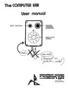
Computer Ear Manual, The - By ARD (Anderson Research and Design) A sixteen-page manual that explains how to use the Computer Ear voice recognition system. An additional four pages include four BASIC type-in programs: Digital Oscilloscope, Flash Math, Speech 1.8 and Speech 4.2. |
|
Composite Video-Out for Astrocade. January 20, 2019. By Justin Pittman. This is a schematic with notes for a composite-out board designed in 2018/2019. Example comparison pictures are included. |
(Michael Matte)_tn.jpg) |
How to Modify an Astrocade Cartridge for EPROM/EEPROM Support. (Modified EPROM/EEPROM Support Videocade: Example) Michael Matte. 2017. Attached is a schematic of a modified videocade (Bally Arcade/Astrocade cartridge) to support/test programmed EPROM/EEPROMs. Michael modified a videocade cartridge and wired it as indicated on the attached schematic back in the 1980s. He may originally have been thinking in terms of EPROMs, but eventually wired a 16-pin header for use with an 9K EEPROM. He also inserted a 32K EEPROM because they're really cheap now. No changes were required. |
(Michael Matte)_tn.jpg) |
How to Modify an Astrocade Cartridge PC Board for a 28-Pin Chip. (Videocade PC Board Modification for 28 Pin Chip: Example) Michael Matte. 2017. Attached schematic shows an example of utilizing a 28-pin EPROM/EEPROM in a standard videocade cartridge. Drawing shows traces cut with a sharp utility knife and rewired. Basic instructions are also included. |
_tn.jpg) |
Installation of Full-Size Keyboard to Astrocade By Ed Larkin. 197x or (possibly) 198x. These instructions give directions on how to connect a Jameco unencoded 63-key keyboard to the Bally Arcade. Keyboards such as this were semi-commonly connected via hackers to the Bally Arcade via the Bally 300-baud Tape Interface. This method wires the keyboard directly to the Bally Arcade's 24-key keypad, thus it doesn't require the tape interface at all. |
|
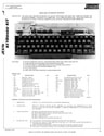
Jameco JE 610 ASCII Keyboard Datasheet These keyboards, from 1979, were often hacked with the 300-BAUD interface to create a keyboard that could be used with Bally BASIC. From the datasheet: "The JE610 ASCII Encoded keyboard kit can be interfaced into most any computer system. The keyboard assembly requires 5V @150mA and -12V @ 10mA for operation. Interface wiring can be made with either a 16-pin DIP jumper plug or an 18-pin (.156 spacing) edge connector." |
_tn.jpg)
|
Lightpen Plans - By Leroy Flamm These are plans, including schematics, on how to build a light pen for the Bally / Astrocade. The documentation refers to a tape with a program for this hardware, but that program has been lost or has yet to be archived. |
(Lance Squire)_tn.jpg)
|
Light Pen Plans - By Lance Squire Quick directions on hooking up an Atari Light Pen to a Bally / Astrocade. |
|
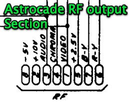
RGB Interface - Midway Note about this scan: It isn't the highest quality... but the original source isn't available. Ken Lill notes on Feb. 26, 2010: "It could be used to give you RGB out of an arcade, but you have to wire into the 3 different supplies and the ground. If you DID use this, you shouldn't need the modulator." Brett Bilbrey notes on Feb. 26, 2010: "That is the schematic for the Midway RGB board. It was a simple board that converted R-Y, B-Y, Video (where in this case, Video is Luma) to the RGB format. I don't know if you can get your hands on one of the boards anymore, but any R-Y, B-Y, Y to RGB converter should work. The nice part of that would be getting rid of the chroma crawl on the NTSC video and you could use the RGB input on newer TV sets. Specifically, the connector that the internal RF modulator (sealed box) mounts to here on the schematic: Astrocade RF Output |
|
R&L 64K RAM Board and Printer Interface - R&L Enterprises Two emails about new hardware that would have been available in the 3'rd quarter of 1996 (it never shipped). It was an Add-On Board with Configurable RAM, EPROM or EEPROM, PS/2 Keyboard Interface, Centronics Printer Interface, and two serial ports. |
